Research overview
The main aim of this project was to demonstrate torsional oscillations resulting from the transfer of angular momentum (AM) from light to matter without absorption and independent of whether the AM is spin or orbital in nature. To achieve this, we developed torsional micropendulums fabricated via direct laser writing (DLW) – a powerful, rapidly evolving additive manufacturing technique based on multiphoton polymerization under ultrafast laser illumination. In the context of AM-driven torsional oscillators, DWL is exceptionally versatile, as it enables precise engineering of the AM-converting component of the micropendulum – in our case, a transparent disk suspended on a thin wire at its center – for optimized optomechanical response to spin, orbital, or both types of AM. Since the seminal 1935 experiment by R. Beth 1 has already demonstrated torsional oscillations driven by spin AM of light using a macroscopic pendulum with a suspended retarder, our project focused on the complementary demonstration involving orbital AM. Specifically, we targeted the non-dissipative generation or conversion of an optical vortex beam, as originally proposed by L. Allen et al. in 1992 2. Despite its long-standing theoretical foundation, this phenomenon had not been experimentally realized until this work, where we designed and fabricated a micropendulum capable of being rotated by non-dissipative optomechanical transfer of orbital AM. The key component of the device is a spiral phase plate (SPP) with azimuthally varying thickness
\[h(\phi) = \frac{\ell\lambda_{\rm pump}\phi}{2\pi(n-n_0)},\]where $\lambda_{\rm pump}$ is the working wavelength, $n$ and $n_0$ are the respective refractive indices of the disk material and the surrounding medium, and $\ell$ is an integer number called “topological charge”. Upon transmission through an SPP, every photon acquires an orbital AM of $\ell\hbar$ and the difference between the input and output AM produces torque on the disk. To measure the resultant angular deviation, we used a probe laser beam focused on the SPP step and sent to a calibrated quadrant photodetector (QPD). The method is detailed in the Optomechanical experiment section below.
Noteworthy, it is also possible to repeat the original Beth experiment on spin AM with our device. For this, SPP should be replaced with a metasurface which converts polarization of the transmitted light due to form birefringence. As shown earlier 3, such microstructures can be readily manufactured by DLW, and the probe method is still viable as it only requires a sharp relief feature near the disk edge.
Model
To establish the theoretical framework, we consider the torsional pendulum schematically depicted in Fig.1. The pendulum is represented by a horizontally oriented disk of radius $R$ and height $H$ suspended from its center on a thin cylindrical wire of diameter $D$ and length $L$. The disk is designed to perform a non-dissipative conversion of the total AM carried by an on-axis (that is, directed along the wire axis, $z$) beam of light, ${\mathbf{J}}_z$. Owing to the law of conservation of AM in the system, the difference in the AM of light, $\Delta {\mathbf{J}}_z$, produces a nonzero torque $\Gamma_z$ on the disk, which thus rotates by an angle $\theta$ around $z$ axis until the driving torque is balanced by the elastic reaction of the wire.
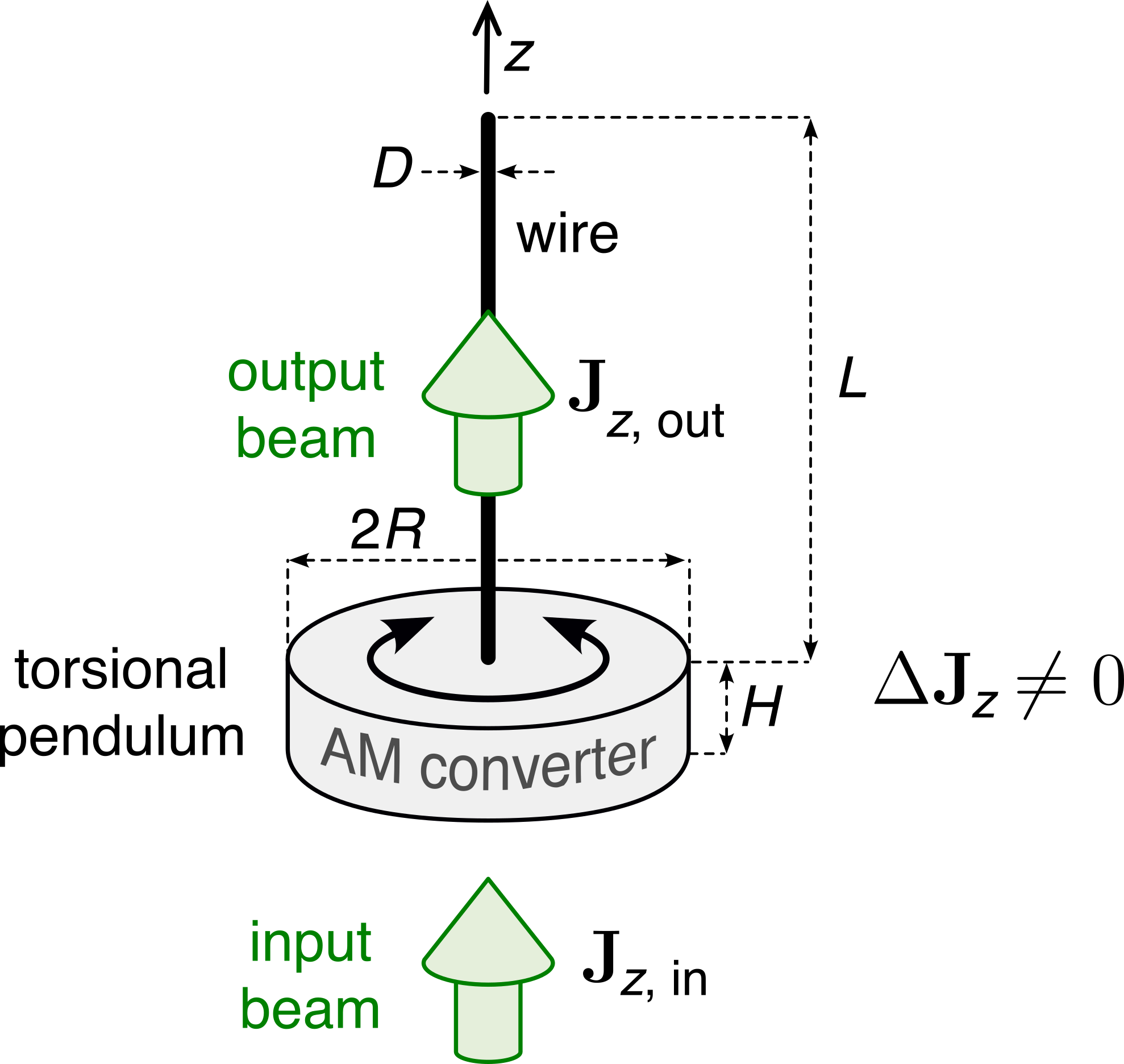
Assuming the linear regime (that is, $\Gamma_z\propto\theta$, which is true for small angular deviations, $\theta<10^{\circ}$), the equation of motion for this pendulum is
\[\begin{align} I\frac{d^2\theta}{dt^2} + \gamma_{\rm damp}\frac{d\theta}{dt} + K_1\theta = \Gamma_z(t), \tag{1} \end{align}\]where $I$ is the moment of inertia of the suspended part of the pendulum along $z$ (neglecting the thin wire, $I \approx m_{\rm disk}R^2/2 = \rho\pi R^4 (H+h/2)/2$ with $\rho$ being the density of the disk material), $\gamma_{\rm damp}>0$ is the damping coefficient, and $K_1$ is the real part of the torsion constant defined as $K = K_1+iK_2$. In the elastic regime, the torsion constants of the wire can be found as $K_{1,2} = G_{1,2}\pi D^4/(32L)$, where $G_1$ and $G_2$ are the real and imaginary parts of the complex shear modulus, $G = G_1+iG_2$. In practice, the driving torque is sinusoidally modulated with an angular frequency $\omega$, and the magnitude $\Gamma_0$, as follows: $\Gamma_z(t) = \Gamma_0\cos\omega t$. Thus, we can rewrite Eq.1 in a more common form
\[\begin{align} \frac{d^2\theta}{dt^2} + 2\lambda\frac{d\theta}{dt} + \omega_0^2 \theta = F \cos\omega t, \tag{2} \end{align}\]where $\lambda = \gamma_{\rm damp}/(2I)$, $\omega_0 = \sqrt{K_1/I}$ is the natural frequency of the pendulum, and $F=\Gamma_0/I$. In this project we are interested in the underdamped regime, $\lambda^2-\omega^2<0$, in which case the general solution of this linear differential equation is
\[\begin{align} \theta(t) = {\rm e}^{-\lambda t} \left(c_1 \cos(t\sqrt{\omega_0^2-\lambda^2}) + c_2 \sin(t\sqrt{\omega_0^2-\lambda^2})\right) + \theta_{\rm p}(t), \tag{3} \end{align}\]where
\[\begin{align} \theta_{\rm p}(t) = \frac{F}{\sqrt{(\omega_0^2-\omega^2)^2 + 4\lambda^2\omega^2}}\cos(\omega t + \phi) \end{align}\]is a particular solution, and
\[\begin{align} c_1 = -F\frac{\omega_0^2-\omega^2}{(\omega_0^2-\omega^2)^2 + 4\lambda^2\omega^2};\,\,\,\, c_2 = -F\frac{2\lambda\omega^2}{(\omega_0^2-\omega^2)^2 + 4\lambda^2\omega^2}; \end{align}\] \[\begin{align} \phi = -\arctan\left(\frac{2\lambda\omega}{\omega_0^2-\omega^2}\right). \tag{4} \end{align}\]Once we let the pendulum stabilize ($t \gg 2\pi/\omega \sim 10$ µs in practice), Eq.3 loses the exponential term and we have the steady-state oscillating solution with the magnitude
\[\begin{align} \theta_{\rm dyn} = \frac{\Gamma_0}{I\sqrt{(\omega_0^2-\omega^2)^2 + 4\lambda^2\omega^2}} \tag{5} \end{align}\]for the dynamic angular deviation.
We distinguish two contributions to the damping; external (energy dissipation due to friction with air) and internal (due to losses within the wire material): $\gamma_{\rm damp} = \gamma_{\rm ext}+\gamma_{\rm int}$. To assess the external part, let us calculate the Reynolds number, ${\rm Re} = \rho_0 v R/\eta$, where $\rho_0 = 1.2$ kg/m$^3$ is the air density, $\eta=2\times10^{-5}$ Pa s is its dynamic viscosity, and $v$ is the maximum speed of the air flow near the disk. During the steady-state torsional oscillations at resonance, the maximum angular speed of the disk is $\omega_{\rm max}=\dot\theta_{\rm dyn}(0)=\theta_{\rm dyn}\omega$, and $v=R\omega_{\rm max} = R\omega\theta_{\rm dyn}$. With typical experimental values of $R=25$ µm, $\omega\sim10^5$ rad/s, and $\theta_{\rm dyn}\sim0.1$ mrad, the Reynolds number is ${\rm Re}=\rho_0 R^2\omega\theta_{\rm dyn}/\eta<10^{-4}$. Following 4, we evaluate $\zeta {\rm Re}^2<10^{-11}$ (where $\zeta\sim10^{-3}$) and conclude that the hypothesis of creeping flow is valid and $\gamma_{\rm ext}=(32/3)\eta R^3$. Taking the internal losses as $\gamma_{\rm int} = K_2/\omega$, we have
\[\begin{align} \frac{\gamma_{\rm ext}}{\gamma_{\rm int}} = \frac{256\eta R}{3\pi D^2 G_2}\sqrt{\frac{L G_1}{\rho H}}. \tag{6} \end{align}\]Preliminary fabrication tests suggested us to take the following values for the geometrical parameters of micropendulums: $R=30$ µm, $H=3$ µm, $L=50$ µm, $D=4$ µm , which correspond to the natural frequency $f_0 = \omega_0/(2\pi)\approx 28$. Then Eq.6 gives $\gamma_{\rm ext}/\gamma_{\rm int}\approx 0.06$, hence we can neglect the external losses and assume $\gamma_{\rm damp} = \gamma_{\rm int}=K_2/\omega$, which gives $\lambda = K_2/(2I\omega)$. Then, dropping the subscripts for simplicity, we get from Eq.5
\[\begin{align} \theta = \frac{\Gamma_0}{\sqrt{(K_1-I\omega^2)^2 + K_2^2}}. \tag{7} \end{align}\]The maximum angular deviation, $\theta_{\rm max}$, occurs at the resonant angular frequency $\omega_{\rm max,\,int}$ for which the denominator of Eq.7 is minimum. This happens when $\omega_{\rm max,\,int} = \sqrt{K_1/I} = \omega_0$, so for such oscillator the resonant frequency coincides with the natural frequency.
Let us introduce the normalized frequency, $\nu = f/f_{\rm max} = \omega/\omega_{\rm max,\,int} =\omega/\omega_0$, and the dimensionless parameter $\gamma=K_2/K_1$ associated with mechanical losses. Then we can write
\[\begin{align} \theta = \frac{\Gamma_0}{K_1\sqrt{(1-\nu^2)^2 + \gamma^2}},\,\,\,\,\,\,\,\,\,\, \theta_{\rm max} = \frac{\Gamma_0}{K_2} \tag{8} \end{align}\]and in the normalized form:
\[\begin{align} \frac{\theta}{\theta_{\rm max}} = {\tilde\theta} = \frac{\gamma}{\sqrt{(1-\nu^2)^2 + \gamma^2}}. \tag{9} \end{align}\]The phase delay (Eq.4) between the pump and the mechanical signal can be expressed as
\[\begin{align} \phi = -\arctan\left(\frac{\gamma}{1-\nu^2}\right). \tag{10} \end{align}\]The material parameter, $\gamma$, depends on the fabrication conditions and cannot be measured directly. Therefore, we express it in the terms of the measurable quality factor, $Q = f_{\rm max}/\Delta f$, where $\Delta f$ is the full width at the half-maximum of the spectrum, ${\tilde \theta}(f)$. From this definition of $Q$ we find
\[\begin{align} Q = \frac{1}{2\left( \sqrt{1+\gamma\sqrt{3}} -1\right)}. \tag{11} \end{align}\]In practice, the measured spectra of the angular deviation magnitude, ${\tilde \theta}(f)$, and the phase delay, $\phi(f)$, are fitted to Eqs.9,10 with $\gamma$ linked to the quality factor according to Eq.11.
Fabrication and characterization
Torsion micropendulums were fabricated by multiphoton 3D lithography using a well-established serial DLW technique 5 6, see the scheme in Fig.2. The working material was the silicon–zirconium hybrid photopolymer SZ2080 (without a photoinitiator to avoid burning by the pump laser beam), drop-casted on a glass cover slip and pre-baked successively at 40, 70 and 90$^{\circ}$ C for 20 minutes in each step. Two DWL systems were used: (i) custom one based on amplified laser Pharos (Light Conversion, Ltd.) with a second harmonic at 515 nm wavelength, 300 fs pulse duration, 200 kHz repetition rate, 50 µm/s writing speed and 0.04 mW average power (pulse energy 0.20 nJ); (ii) commercial Nanofactory workstation (Femtika) based on the femtosecond oscillator Flint (Light Conversion, Ltd.) with a second harmonic at 517±10 nm, 144 fs pulse duration, 76 MHz repetition rate, 100 µm/s writing speed and 4.7 mW average power (pulse energy 0.06 nJ). In both systems the beam was focused through a 63x oil-immersion microscope objective lens (Plan Apochromat Zeiss) with a numerical aperture of NA = 1.4, thus producing intensities around 0.84 TW/cm$^2$ and 0.68 TW/cm$^2$ for the systems (i) and (ii), respectively.
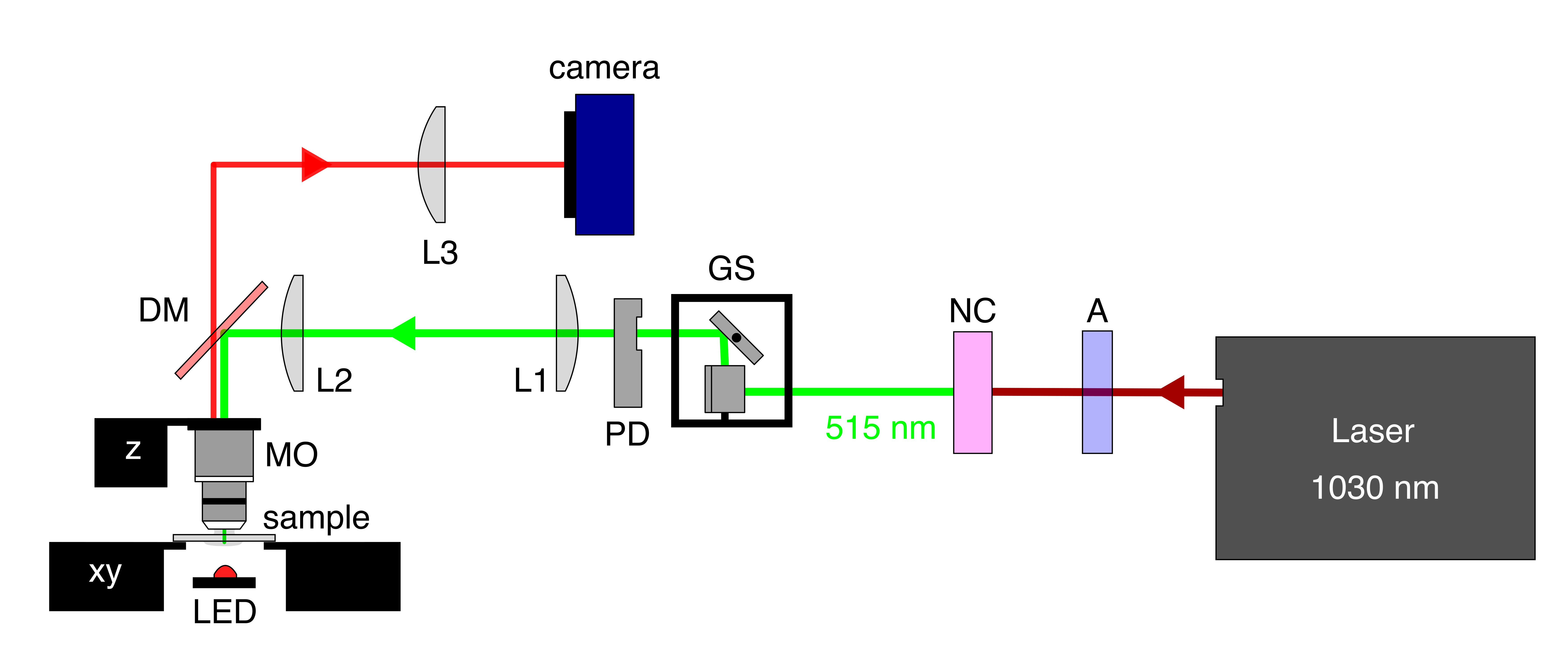
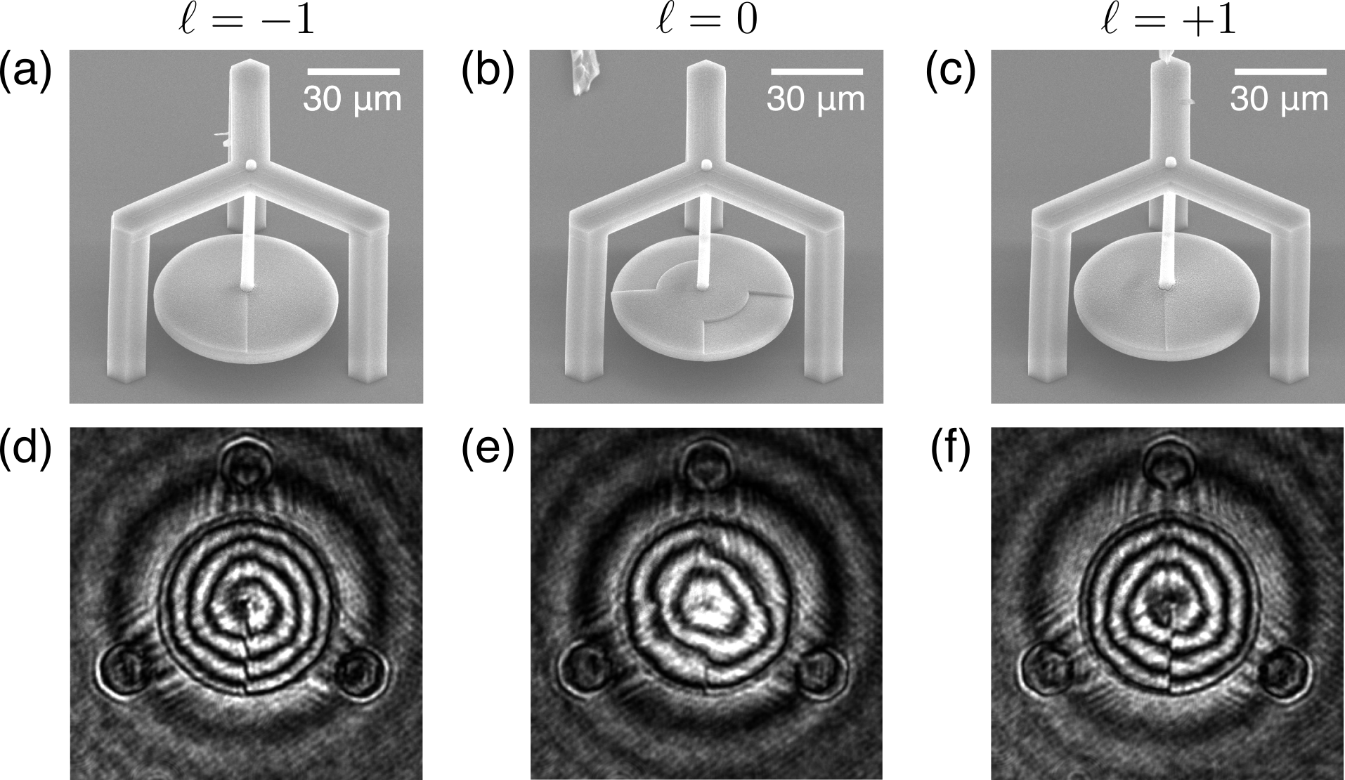
The DLW process was controlled using 3D Poli software (Femtika) with a custom script to produce each microstructure layer by layer. To ensure smooth polymerization, the scanning was done with concentric circles for the wire, and concentric helices for the SPP. Fabrication of a single micropendulum structure took approximately 3 hours. After exposure, each sample was developed in acetone for 1 hour, rinsed in ethanol, and dried using critical point drying (CPD, Quorum K850) to minimize the damaging effects of surface tension on the wire and disk orientations. For inspection purposes, test samples were coated with about 20 nm of silver and imaged using a scanning electron microscope (SEM, Prisma E from Thermo Fisher Scientific). Typical images are shown in Fig.3(a-c), where the middle structure is the ‘null’ pendulum, which includes vertical steps (required for rotation detection) but lacks an SPP ramp and is therefore not expected to produce orbital AM conversion. The micropendulums had the parameters given above, except the designed wire thickness which was set to $D = 2.7$ µm because the fabricated wires were consistently measured to be thicker than the designed ones. The SPP step height $h = \lambda_{\rm pump} / (n - n_0)$, where $\lambda_{\rm pump}=532$ µm, $n=1.504$ and $n_0=1$. are the refractive indices of the polymer and the surrounding medium (air), respectively. In the ‘null’ pendulum, the steps were designed to have the same height, $h \approx 1.055$ µm. The driving torque was modeled as $\Gamma_0 = \ell \lambda_{\rm pump} P/(2\pi c)$, where $c$ is the speed of light in vacuum and $P$ is the intercepted optical power.
Optomechanical experiment
The optoelectronic system for the pump-probe experiments with torsional micropendulums is schematically shown in Fig.4(a). The experiment consisted of exciting torsional oscillations by illuminating a micropendulum with a linearly polarized, focused Gaussian beam (Verdi V5, continuous-wave at 532 nm) directed along the wire axis ($z>0$) through the flat underside of the disk. Based on the specifications of the focusing aspheric lens (AL, Thorlabs AL2520-A) and the measured incident beam diameter of 0.943 mm, we estimated the Rayleigh range to be 303 µm and the beam waist $w_0 \approx 7.2$ µm - approximately half the radius of the flat central disk in the ‘null’ sample, $R_0 = R/2$, as shown in Fig.4(c), hence we assumed $P=P_{\rm pump}$.
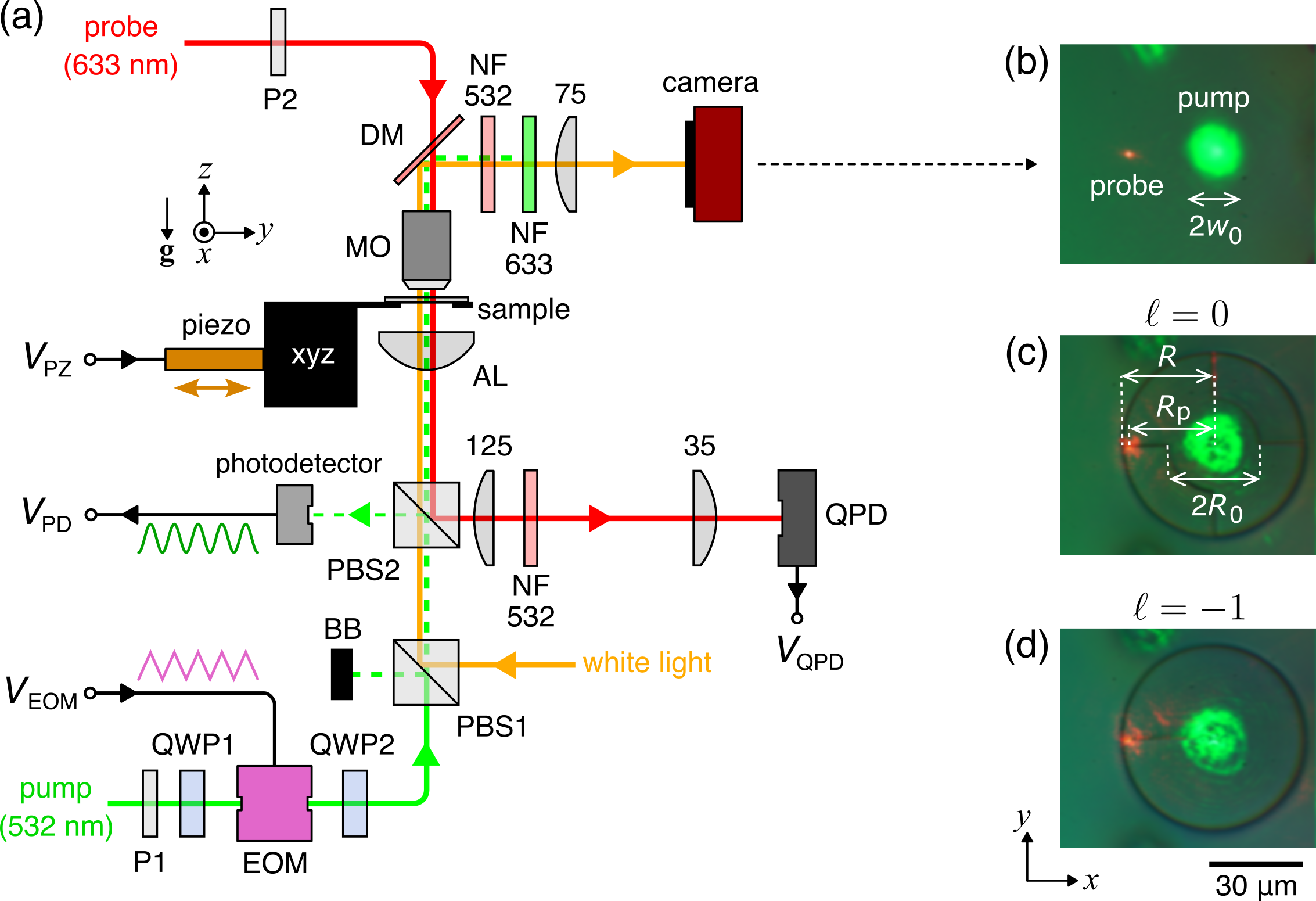
To explore resonant excitation, the pump beam was modulated by an electro-optical modulator (EOM, Thorlabs EO-AM-NR-C4) placed between two quarter-wave plates (QWP1, QWP2), whose orientations were set to maximize amplitude modulation in transmission through the polarization beam splitters (PBS1, PBS2). The periodic driving voltage ramp, $V_{\rm EOM}$, was produced by a function generator and amplified 20x using a high-voltage amplifier (Thorlabs HVA200). At a driving voltage amplitude of 4.9 V, the modulated pump power $P_{\rm pump}$ achieved a maximum contrast ratio of approximately 30:1, see Fig.5(a). During the experiment, $P_{\rm pump}$ was monitored in situ using a calibrated photodetector (Thorlabs PDA55). The sample was imaged in transmission under white-light illumination (in the Köhler configuration) using a high-NA microscope objective (MO, Olympus LMPlanFL N, 100x, NA=0.8), with the image projected onto a CMOS camera (Thorlabs Zelux CS165CU).
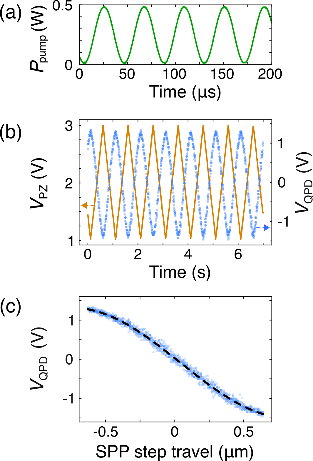
To detect the light-induced angular deviations of the micropendulum, we used a probe beam (He–Ne laser, 633 nm wavelength) tightly focused by the MO onto the step on the top side of the disk, as close to the edge as possible [$R_p \to R$ in Fig.4(c,d)], in order to minimize measurement errors. The transmitted probe beam was relayed to a quadrant photodetector (QPD, Thorlabs PDQ80A with KPA101 cube controller) to monitor the centroid of the self-interference pattern. For small rotations around $z$, displacements of the step along the $y$-axis are proportional to the output differential voltage of the QPD, $V_{\rm QPD} = (V_{Q1}+V_{Q2})/(V_{Q3}+V_{Q4})$, where $V_{Q1-4}$ are the voltage readings from the four quadrants. To determine the proportionality coefficient, $\alpha_{\rm cal}$, for each micropendulum, we performed a calibration using a piezo stack (Thorlabs PK4GA7P2) that pushed the sample stage along $y$ against a spring. During this calibration, a voltage ramp $V_{\rm PZ}$ was applied to the piezo stack, and $V_{\rm QPD}$ was recorded as a function of time, $t$; a typical series is shown in Fig.5(b). The QPD calibration factor (in this case, $\alpha_{\rm cal}\approx-0.35$ µm/V) was then obtained as the slope of $V_{\rm QPD}$ versus the step travel distance (which was determined from camera images at set $V_{\rm PZ}$ values), see Fig.5(c). Since the relationship is linear only near the central region, the slope was extracted by fitting the data to a sinusoid. Notably, the actual light-induced travel of the step is on the order of 1 nm, which is way below the resolution limit of the imaging system, and yet easily detectable by the QPD.
Results
Upon first exposure to the modulated pump beam, a typical response near resonance exhibited a magnitude of ~100 mV – readily measurable by an oscilloscope – while low-frequency noise manifested only as slow baseline shifts over multiple torsional cycles. However, this strong response proved transient. We consistently observed a gradual decay in oscillation amplitude, stabilizing at a level approximately 30 times lower than the initial value after about an hour of continuous exposure. We attribute this behavior to ongoing laser-induced cross-linking of the photopolymer. To ensure long-term stability of the optomechanical response, we pre-exposed the full disk area of each micropendulum to the pump laser at a peak intensity of 0.5 GW/cm$^2$ (lower than the sample receives in the pump-probe experiment) for at least two hours. As a result, the torsional signal became stable in time but too noisy for spectral measurements of acceptable quality. Therefore, we extracted the signal’s magnitude and phase delay using a lock-in amplifier (Signal Recovery 7280 DSP), while scanning the modulation frequency $f$ and taking $V_{\rm PD}$ as an external reference. Mechanical noise was suppressed with a high-pass RC filter (cutoff at 40 Hz). The measured magnitude, $M(f)$, provides the spectrum of the angular deviation magnitude, $\theta(f) = M(f)A_{\rm s}\alpha_{\rm cal}R_{\rm p}$, where $A_{\rm s}\approx 39$ is a scaling factor determined by comparison with oscilloscope measurements, and $R_{\rm p}\approx 27$ µm is the distance from the disk center to the probe spot.
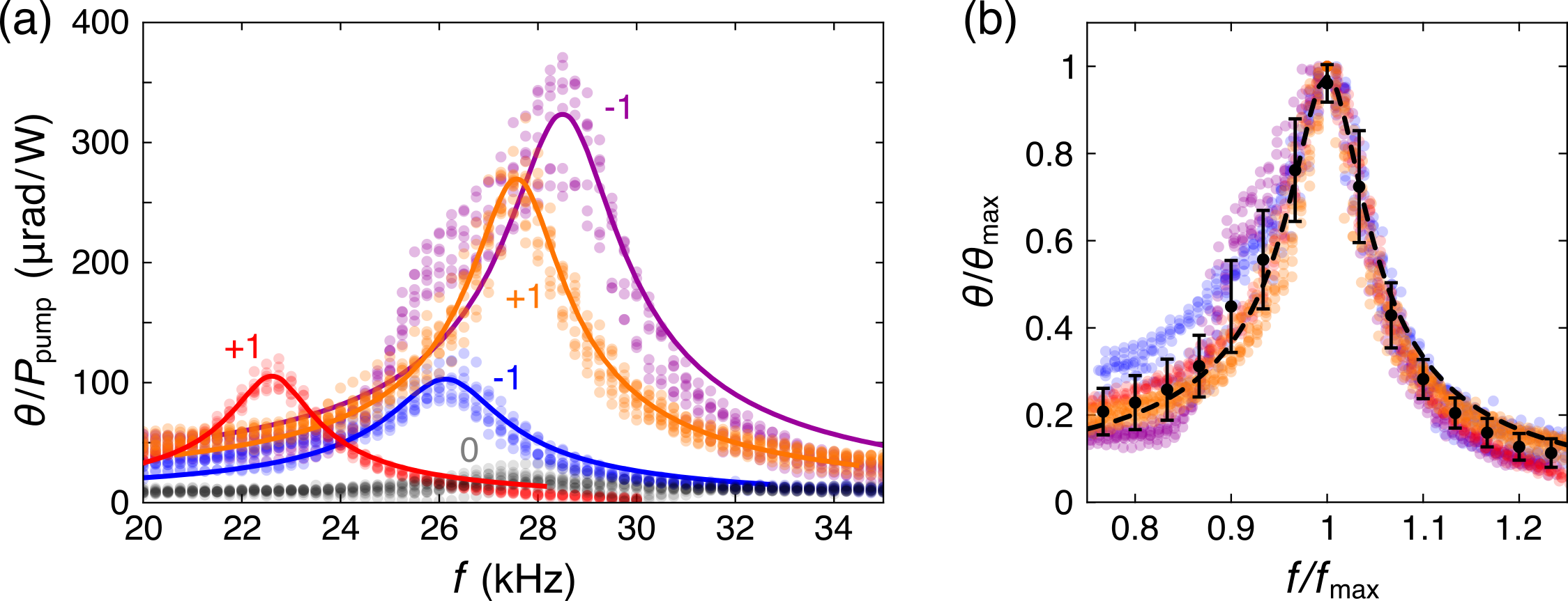
Typical measured spectra of the micropendulums with SPPs are shown in Fig.5(a) where the color markers are the experimental data points and the solid curves represent the best fits to Eq.9. As one can see, the spectra have similar resonant frequencies (namely, they are within 10% from the mean value of 26.25 kHz), thereby confirming reproducibility of the key geometrical ($I$) and mechanical ($K_1$) parameters of the device. The quality factor was quite reproducible as well, with the value $Q=8.06\pm0.72$ extracted from these fits. When combined in a normalized graph [Fig.5(b)], the spectra measured from different SPP micropendulums fit reasonably well into a single master-curve.
Besides the demonstration of the optomechanical effect itself (that is, $\theta>0$), the key experimental result of this project is the significantly (at least an order of magnitude) weaker response of the ‘null’ micropendulums compared to the devices with SPPs, see the gray vs. color markers in Fig.5(a). Theoretically, ‘null’ pendulums are not expected to acquire any light-induced torque because for them the input and output AM are equal to each other. In practice, however, the signal is always nonzero, because the structures never have the expected perfect mirror symmetry, and, being free-to-rotate mechanical oscillators, they would amplify any directional disturbance, including noise, near their natural frequencies.
More results to appear here after publication…
-
R. A. Beth, “Mechanical Detection and Measurement of the Angular Momentum of Light,” Phys. Rev., vol. 50, pp. 115–125, 1936. ↩
-
L. Allen et al., “Orbital angular momentum of light and the transformation of Laguerre-Gaussian laser modes,” Phys. Rev. A, vol. 45, pp. 8185–8189, 1992. ↩
-
S. Varapnickas, S. C. Thodika, F. Moroté, S. Juodkazis, M. Malinauskas, and E. Brasselet, “Birefringent optical retarders from laser 3D-printed dielectric metasurfaces,” Appl. Phys. Lett., vol. 118, no. 15, p. 151104, Apr. 2021. ↩
-
B. Sanchez-Padilla and E. Brasselet, “Torsional Mechanical Oscillator Driven by the Orbital Angular Momentum of Sound,” Phys. Rev. Appl., vol. 13, no. 6, p. 064069, Jun. 2020 ↩
-
E. Brasselet, M. Malinauskas, A. Žukauskas, and S. Juodkazis, “Photopolymerized microscopic vortex beam generators: Precise delivery of optical orbital angular momentum,” Appl. Phys. Lett., vol. 97, no. 21, p. 211108, Nov. 2010 ↩
-
S. Varapnickas, A. Žukauskas, E. Brasselet, S. Juodkazis, and M. Malinauskas, “3D microoptics via ultrafast laser writing: Miniaturization, integration, and multifunctionalities,” in Three-Dimensional Microfabrication Using Two-Photon Polymerization, I. Sakellari, Ed., Amsterdam, Netherlands: Elsevier, 2020, pp. 445–474 ↩